Pico smart battery charger project not working #4894
Replies: 1 comment
-
|
Posted at 2020-06-08 by @allObjects @user113488 that's about what you should see in the left pane of the IDE: I assume you did the following:
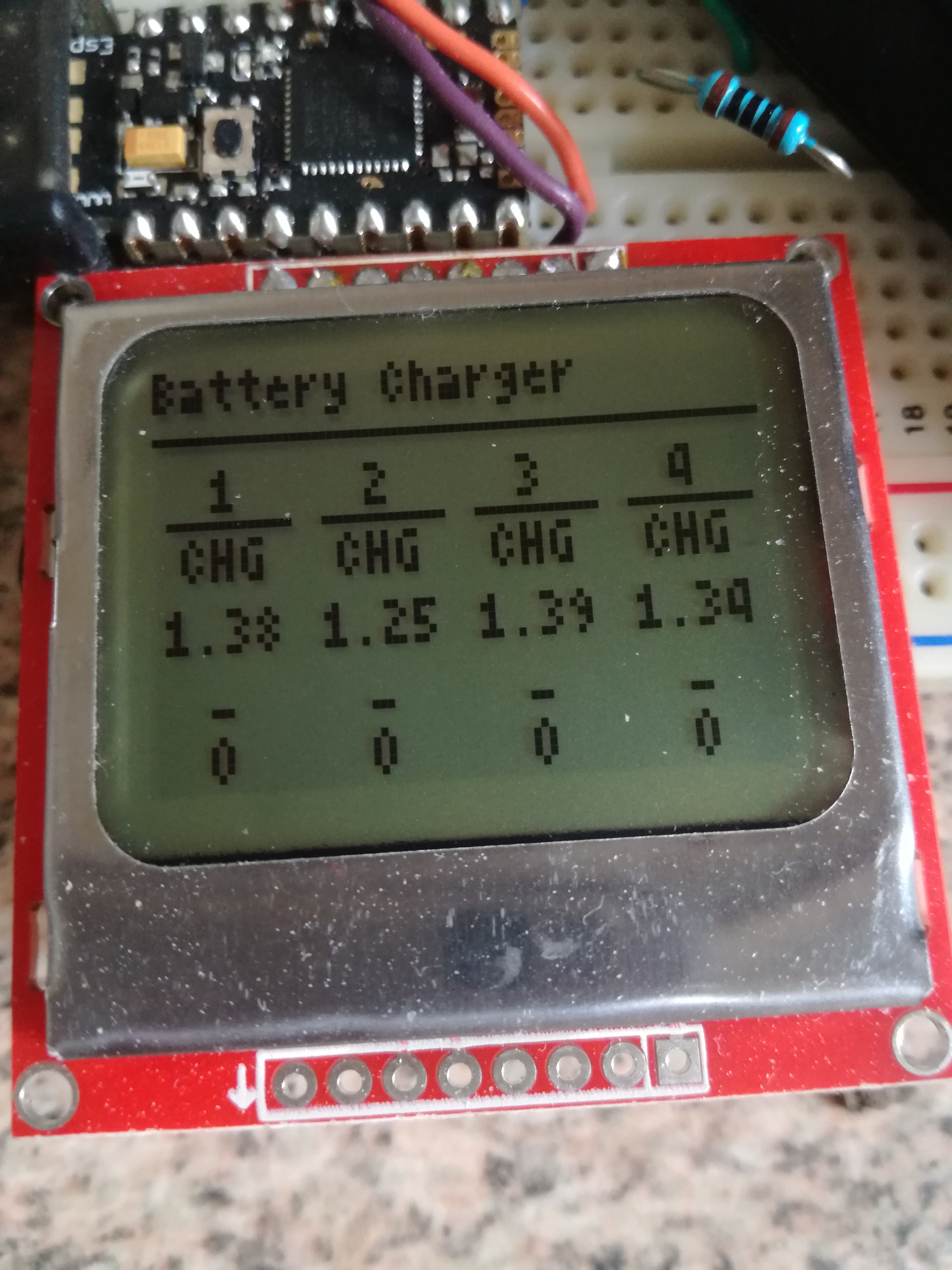
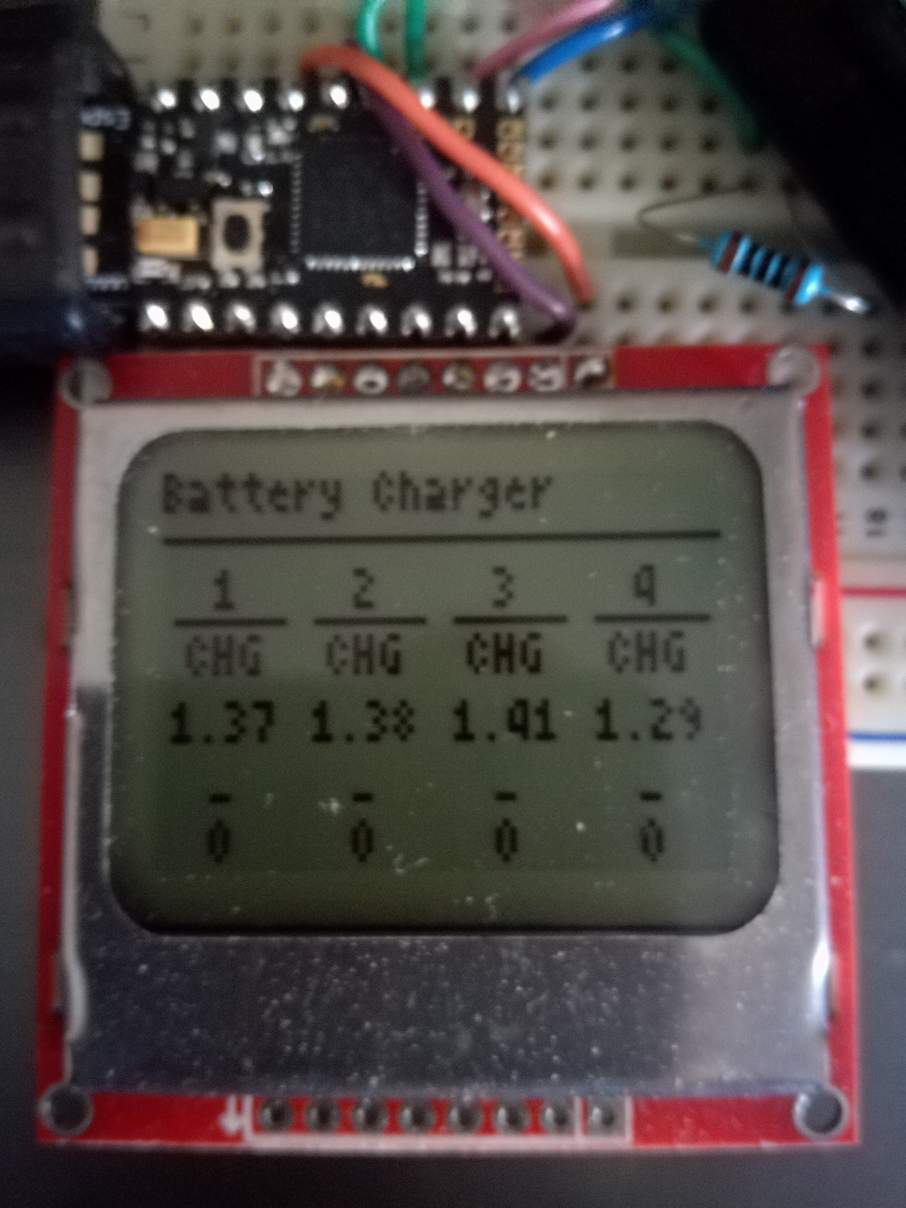
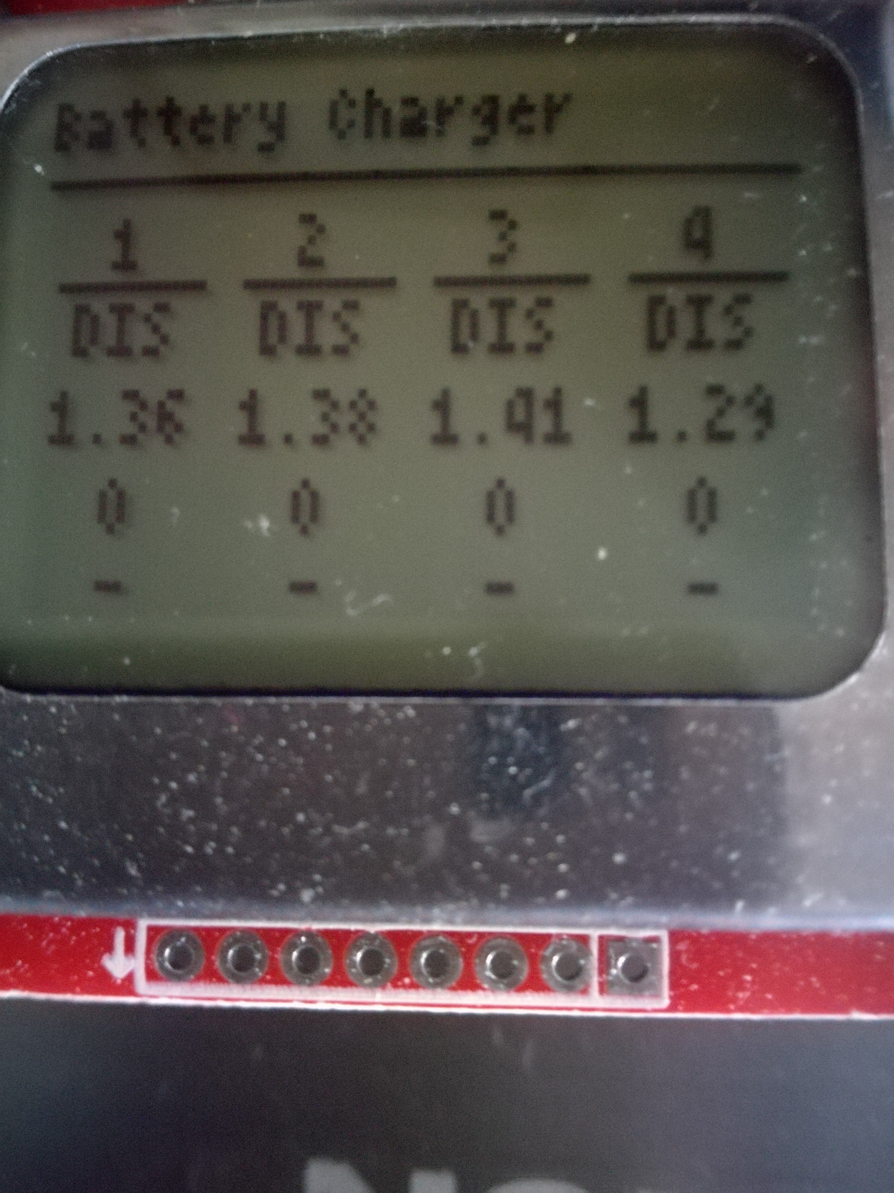
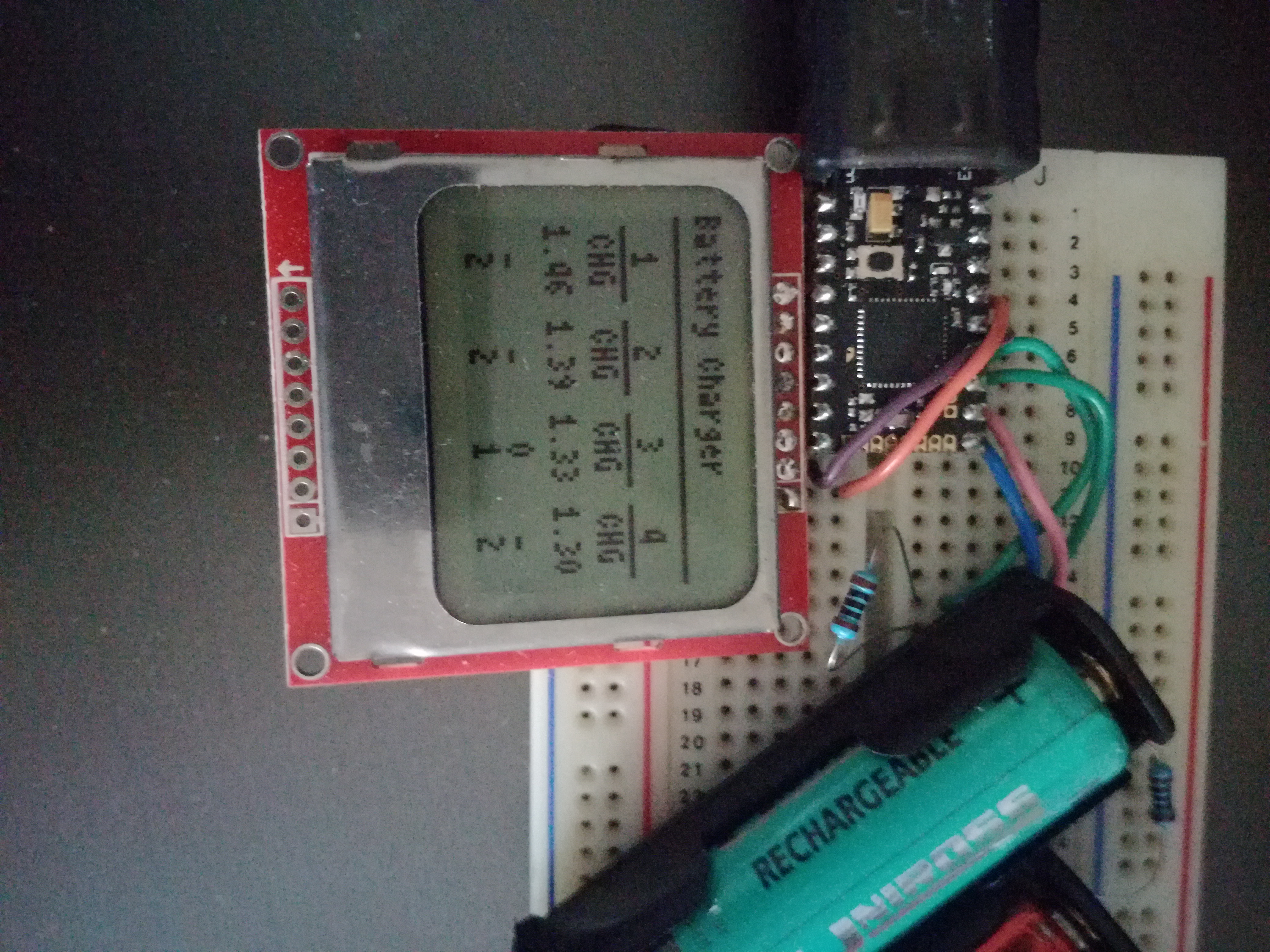
I have tested with most recent build 2v05.155, but I assume you have the release 2v05, so I reinstalled the 2v05 release, and for both versions it runs as expected (with no batteries connected). So far I did everything connected. The save() command stores the uploaded code in the FLASH for good, so when disconnect and reconnect again, Espruino knows what to run. So I tested this as well... While disconnected and powered - with some 5V USB charger - you do not ave the console output. But when repowered with USB from computer, you can (re-)connect and you should get this in the console: What exactly happened in your case I cannot say. But: did you type save() in the right pane and then upload? ...or do you have a different setup, such as save on upload enabled? I usually do not do that. 'I keep the right to say save() at my terms', not on upload. Posted at 2020-06-10 by user113488 Thanks for the quick reply. Since my original post I got it working with a phone charger, but it went off when I touched it. After a couple of attempts it loaded again successfully and I've left it on since then. The breadboard I'm using is 30 years old and hasn't been used recently, so I put this down to poor connections. I get similar a response when I connect to the computer. I'm using the Chrome app on Ubuntu 20.04, so that could account for the difference. The display on the charger does not work as described though. The bottom two lines remain as zero, though they went to dashes with one set of batteries I tried. When I flashed the Pico it gave me three options for the firmware to install. I chose the top one with everything. Could that make a difference? Thanks again. Posted at 2020-06-11 by @gfwilliams Could you post up a picture of the screen? The top firmware (everything) should be the one you want. That all seems ok. Plus I use Chrome on Ubuntu for everything so I imagine that is ok too. However, did you see the 'Linux users' bit on: http://www.espruino.com/Quick+Start+USB#plugging-in You need to add a file that tells Linux not to try and connect to it as a modem. That might explain your Posted at 2020-06-19 by user113488 Thank you for your reply Gordon, I did add the bit to the rules in Ubuntu. I've been observing for a week now and things are changing. I suspect that the connection with the breadboard might be at fault because when I move it sometimes the screen goes blurred and it has restarted once. Thanks for your help on this. Attachments: Posted at 2020-06-20 by @allObjects Be aware of the 6.2 Absolute maximum ratings, Table 12 - on page 62 in the datasheet - of the Espruino Pico STM32 chip https://www.espruino.com/datasheets/STM32F401xD.pdf To stay within the logic level specifications, an IO pin cannot drive more than 25mA - source or sink - and the whole chip cannot more than a total of 120mA... If you go for more, the chip first browns out and then may get damaged... I have a suggestion for a nice enhancement for this Battery charger: measuring the charge current! Tip how to go about that: put the resistor on the low side instead of the high side and measure the voltage drop on the resistor with additional ADC pin of which there are plenty of left to do so (5). The resistor has of course to be a precision resistor. Switching the resistors onto the low side, may require a change in the software depending how it does the measuring of the voltage. You have to change how you measure/calculate the voltage - charge state - of the battery when you measure while it is charging: you subtract the voltage drop over the resistor. Posted at 2020-06-23 by @gfwilliams @allObjects actually a really nice addition would be to stick on the DRV3388 motor driver than you mentioned in another thread (http://forum.espruino.com/conversations/349688) and then also measure the voltage across a resistor. Interestingly I'd found using the battery charger @user113488 has made worked pretty well on some older AAA and AA batteries. I tried moving to a newer Ikea battery charger and it just wouldn't touch them, but this one at least gets them to a usable (if not great) charge. I think being able to force a bit more current into them would really help to put a bit more life into them though Posted at 2020-06-23 by @allObjects @gfwilliams, quite interesting thought... Had forgotten to mention that putting the resistor in the low side, the voltage sensor ADC input pins have to be put on voltage divider resistor-pair to make sure nothing bad can happen to the chip an make it work for any Espruino board (voltage test point - 2.2k - Espruino pin - 3.3k - GND for save 5V max / 0.9mA @ 5V ; 1.8k instead of 2.2k, 1mA @5v can work. For lesser 'side-load', use 4k7 and 6k8 or 9k1 and 12k - to stick w/ E12 value series. Precision resistors come though in many different ways). Not having precision resistors at hand is no problem at all, because that's where software can kick in and make it work: with multi-meter of decent sensitivity and precision - and practically all digital multimeters qualify for that - you measure the components and adjust the calculations for each of the four circuits. Back to the idea of putting a DRV3388 to work, add a diode in charge direction on the high side of each charge circuit to prevent any challenges. One single DRV3388 can actually drive 4 circuits with only one caveat: switching on and off goes only for pairs... after a pair has switched off, the fully charged one has to be taken off to complete the remaining one. Software can sense an 'occupied' slot. Here the schema for one charging device. The R_on min is specified as 180 mOhm but doing some experimenting over the range of charge current has to be measured and taken into account in voltage / charge current calculation. One could also use a full DRV8833 H-Bridge for a single charge circuit and add option of 3 different charge currents by putting diodes into the low side / drain path. This makes the calculation more difficult because of the current dependent voltage drop of diodes, but it is still manageable. With 3 of the four output options and two different current limiting resistors 3 different charge currents can be established, of which - of course - two are dependent, like 10%, 90% and 100%. As useful a the DRV8833 is, a low gate threshold NMOS FET array (TI TPL7407LA or ULN2004 Darlington Transistor Array - or even just 4 standalone low threshold NMOS FETs - can do the job equally well since software has to 'compensate' anyway for the components' dependent behavior (@MaBecker, what are your double-targeted thoughts/comments?) |
Beta Was this translation helpful? Give feedback.
Uh oh!
There was an error while loading. Please reload this page.
-
Posted at 2020-06-07 by user113488
I bought a pico to build the smart battery charger in the projects. I haven't a clue what I'm doing so I followed the instructions from the page. I updated the firmware to 2v05 and pasted in the code from the instructions. Nothing happens. I tested the continuity of all the connections and they are okay. I plug in the USB, the red light blinks and nothing else happens.
If I connect to the web ide I get this:
Loading 6445 bytes from flash...
Running onInit()...
Hope someone can help bearing in mind my knowledge of coding is practically zero.
Thanks in anticipation
Beta Was this translation helpful? Give feedback.
All reactions