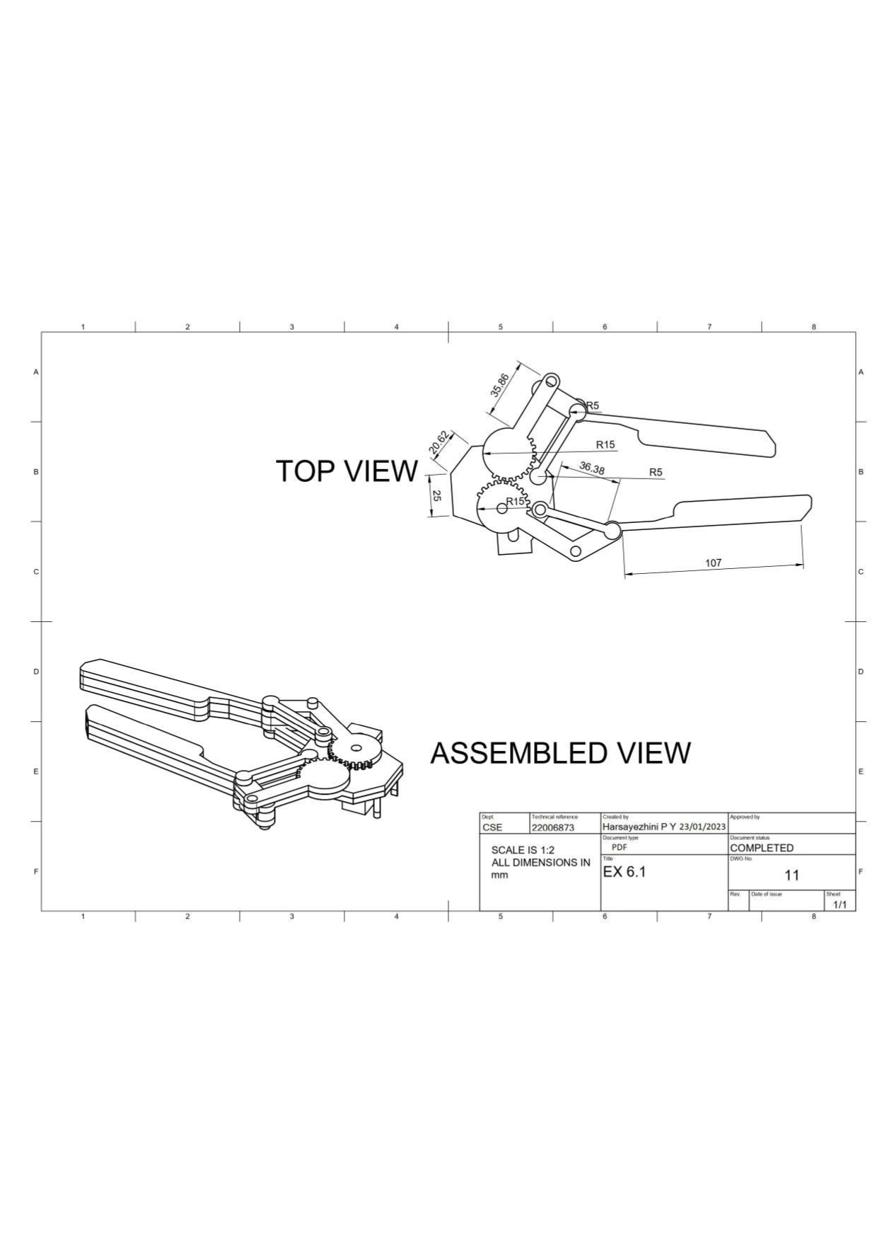
To Design the various parts of a mechanical component and assemble it using a bottom-up approach then convert it into the orthographic view
- Autodesk fusion 360
- Windows 10
- 4 GB of RAM (integrated graphics recommend 6 GB or more)
- 2.5 Mbps or faster download; 500 Kbps or faster upload
The Align tool allows you to align, distribute or organize selected elements, annotations, tags and text along the axis you specify. Furthermore, the Arrange feature will automatically neatly place your tags around the current view. The Align plug-in for Autodesk® Revit® can help to save time while producing complex drawings with large sets of annotation. Just select a few elements and the Align tool will sort them for you.
Insert design elements such as Components, Bodies, Sketches, Work geometry, Flat patterns or parameters from another design. The inserted elements update with changes to the original design
Move: Moves the selected face, body, sketch, or construction geometry a specified distance or angle.
Select the objects to modify then specify the distance or angle. Use set pivot to reposition the manipulator
Identifying the given model.
Firstly, we import all the necessary parts into the assembly project. Here, we use Finger, gear linkage, Secondary Linkage, Base. For, Importing the components into the project, we use the insert derive option in the Insert>Insert Derive.
We place the base model onto the X-Y plane.
Then we align the imported, Gear linkage model, in its respective slot of the base. For aligning the component onto the base, we use the align option, available in Modify>Align. For aligning the component onto the base, we first select the “from” coordinates then we select the “To” coordinates in the given base model. At first, the model might not align properly, so, we use the flip option to bring the component to the desired position.
We follow the same steps for aligning the components onto their respective slots on the base component.
If the components do not fit properly into the slots, it can be moved into the slot using the Move option.


Thus, a design of various parts of a mechanical component and assemble it using a bottom-up approach in orthographic view has been done