Front Panel Expansion Connector
The QA402 and QA403 have a front-panel expansion connector. The pinout between the two is slightly different. Over time, more support will be added to the panel, but we cannot guarantee the ultimate functionality that will arrive as it will be an iterative learning process.
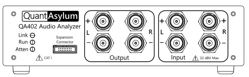
The expansion connector is located on the front-panel, to the right of the status LEDs:
The pinout of the connector is shown below. Be aware that there are earlier versions of this drawing floating about. This drawing below should be considered definitive.
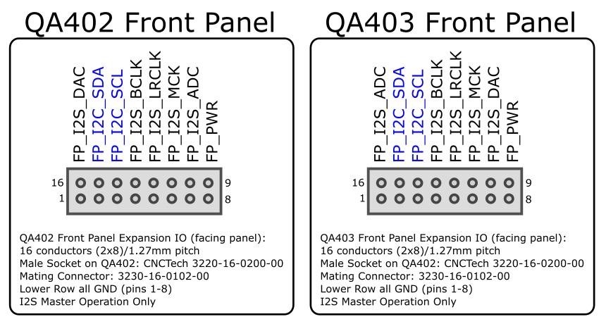
The signal descriptions for the QA402 and QA403 (also known as the QA40x hardware) are as follows (other analyzers might have different pin-outs OR functionality).
FP_I2S_DAC: This is the output bit stream from the QA40x. It is nominally a 3.2V digital signal.
FP_I2C_SDA: This is the bidirectional I2C data line.
FP_I2C_SCL: This is the output I2C clock line.
FP_I2S_BCLK: This is the output I2S bit clock. Typically, this is will be either 32X or 64X (depending on bit width) of the sample frequency.
FP_I2S_MCK: This is the master clock output, typically 24.576 MHz.
FP_I2S_ADC: This is the I2S ADC data. This should be left as "NC" on your board as the signal will present as GND.
FP_PWR: This is a small source of power that can be used to drive an digital isolator (see the schematics).
The FP_PWR will be enabled when the QA40x is plugged in. It will appear as a 3.2V source with a 10 ohm series resistance. You should not pull more than 10 or 20 mA from this pin, which is enough to drive an isolator or two.
The expectation is that you will create an adaptor board to convert the QA40x expansion signals to signals you can use on your DUT. Part of that effort should include isolation. In the sample schematic below, note the A side of the isolators are powered from the ISO_PWR provided by the QA40x. The A-side of the isolators is the lower-current side. The B-side of the isolator requires a bit more current.
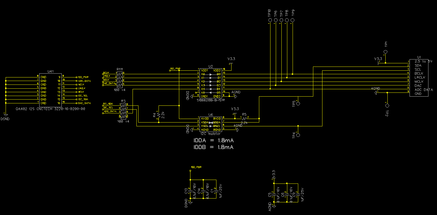
The schematic above (for the QA402, the QA403 has a slightly different connector pinout) will allow your DUT to operate between 2.5V and 5.5V, and provides a good isolation barrier such that the insulation between the QA402 side and the DUT side of the circuit will readily deliver > 10 GOhm @ 1KV of insulation testing. If you are building a board similar to what is shown for your own DUT, please feel free to contact us for review if you'd like.
The ultimate speeds supported are as of yet unknown, but 48 kHz sampling rate and 16- and 32-bit word width is functioning in current releases.