SPKR THD versus Frequency
The SPRK THD versus Frequency plug-in will allow you to drive a speaker to two thresholds of distortion. The hardware setup for the test is shown below:
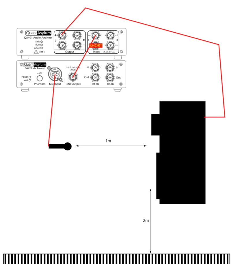
In the image above, the speaker is shown as self-powered, but might also be driven by an amplifier.
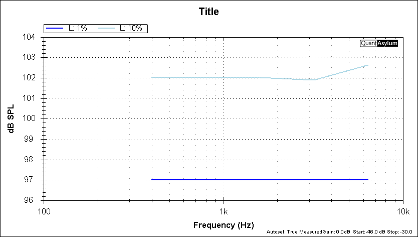
The resulting plot appears similar to what is shown below. Note that we can read the speaker output SPL achieved for both 1% or 10% distortion.
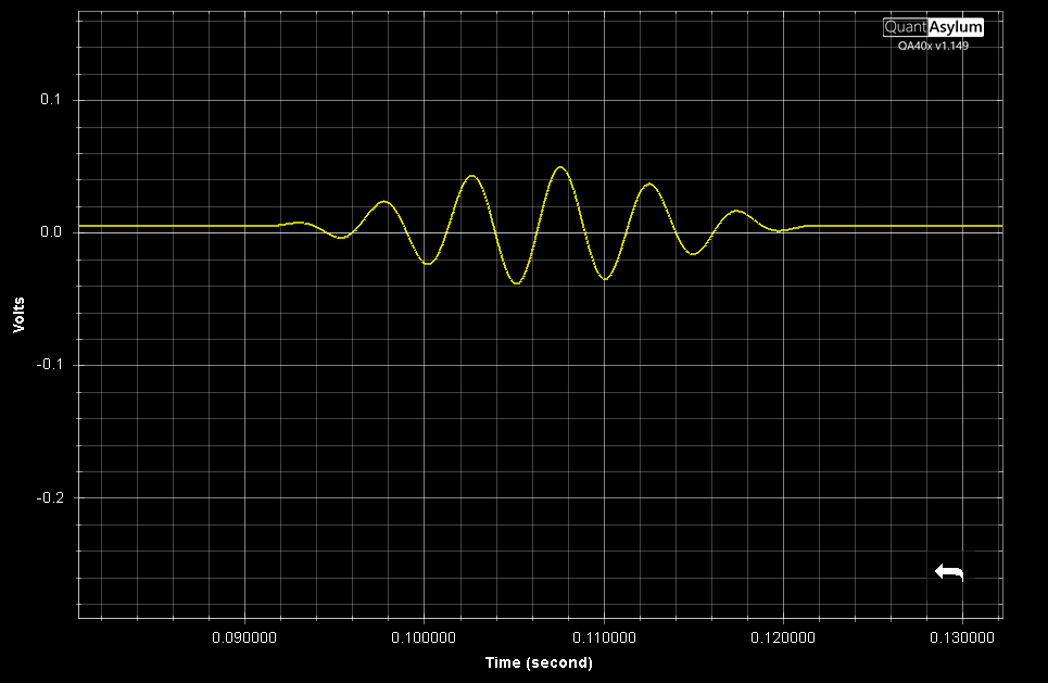
The stimulus is a Hann-windowed tone burst with a duration and type specified by the user. Below, is the time domain of ~6 kHz tone with a 185 mS burst duration.

We could also opt for a CEA-2010-A burst, which will always give a specified number of cycles (usually 6.5). This means lower frequencies have a longer burst than higher frequencies. A 200 Hz CEA-2010-A burst (6.5 cycles) is shown below:
Regardless of the burst type, the peak burst voltage (after DC removal) will be used for the peak SPL calculation. So, if the waveform peak is 1.41V at the tip of the sine, and your mic sensitivity is -40 dBV @ 94 dBSPL (10mVrms @ 94 dBSPL, or 14.1mVpk @ 94 dBSPL), that means your incoming signal is 40 dB stronger than the reference, and so your dBSPL will be 40 dB higher--134 dB SPL in this case.
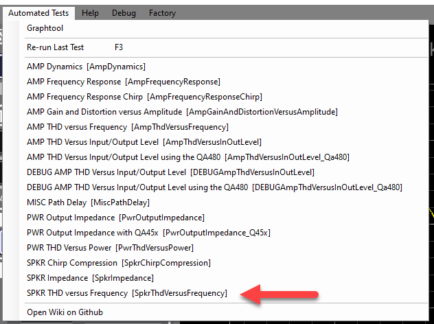
The test is selected from the Automated Test menu:
The options for the test are shown below:
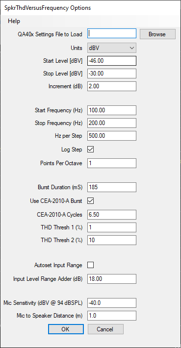
Here, we can specify the Start Level, Stop Level and Increment. When settings these values, make sure you understand the level required that will potentially damage your speaker. Also, the increment should be set to a small value, such as 1-2 dB. If your increment is set too large, then in a single step your speaker might go from distortion well below 1% to distortion well above 10% and you could damage your speaker.
The Start Frequency and Stop Frequency allow you to control the frequency range of the sweep. Note that each frequency will be tested to the threshold you specify before moving on. If the measured distortion exceeds your specified threshold for THD Thresh 2, then the current frequency will stop early and the test will move to the next frequency. If the THD Thresh distortion level is never seen by the test, then that frequency will be empty in the graph.
If you check Log Step, then you can specify the number of points per octave. If you don't check the Log Step, then the test will proceed by adding a fixed frequency to the current frequency when it's time to move to the next point.
The Burst Duration (mS) allows you to specify the time duration of the burst. If you opt for a CEA-2010-A-Burst, then the burst width will be a specified number of cycles (usually 6.5 cycles).
There are two THD thresholds to specify: THD Thresh 1 (%) and THD Thresh 2 (%). You may specify value from 0.1% (-60 dB) THD to 31% (-10 dB) THD. The units are always percent and cannot be changed. But as a quick source of conversion, the typical values are listed below:
-60 dB THD = 0.1%
-40 dB THD = 1%
-20 dB THD = 10%
-10 dB THD = 31%
The Autoset Input Range checkbox will automatically adjust the full scale input level if requested. When checked, before the measurement is run a measurement will be made and the gain of the system will be be determined. And then, the full scale input will will be automatically adjusted to ensure the incoming signal is at least the specified level (in the Input Level Adder (dB) field.
The Mic Sensitivty is about -40 dBV at 94 dBSPL. This is provided by the manufacturer. We did NOT use a calibrated mic on this measurement. But if we did, we'd use the 1 kHz figure that came with the calibration certificate and we'd also load a user-weighting of the calibration file before we ran the plug-in.
Finally, the distance between the mic and speaker is set to 1m in the Mic to Speaker Distance (m) field. This will adjust the plotted SPL level. 1m of distance will result in no adjustment to the plotted data. If you specify 2m, the plotted data will increase by 6 dB to account for the increased distance. The plug-in applies a far-field correction factor of 6 dB per doubling if distance.
By knowing the above, we can readily compute dBSPL. We know that the mic produces -40 dBV for a 94dBSPL signal. That is gained up to 20 dBV by the QA470. We can then add (94 + 20) = 114 dB to the measurement to get the level in dBSPL. The gain of any mic preamp is set in the "input gain" section of the dBV context menu (right click on the dBV button in the Axis control group on the main screen).
This is the benefit of using no-cal equipment with fixed, known gains (QA470 and QA401) that don't have gain adjustment knobs.
Most active mics will have an acoustic overload point (AOP) of around 130 dBSPL. If you want to know where you mic hits its overload point, then move the mic directly in front of the speaker on the cabinet. The move from 1m to nearly contacting the grill will increase the level into the mic by about 40 dB. This will let you see where the mics overload as the mics will exhibit their own curve compression.
If you are using a dynamic mic (such as SM57) then the overload point of that mic will be far beyond 130 dB and you won't need a pre-amp either.
Keep in mind that if the mic delivers -40 dBV at 94 dBSPL, then at 130 dBSPL you are approaching 0 dBV out of the mic. With the +20 dB gain from the mic preamp, that's nearly 20 dBV out of the mic preamp. Know where your mic preamp clips! Most mics cannot handle this and will need to be moved back (and reflection times adjusted), or a lesser pre-amp gain should be used.
The key is that you need to be aware of the signal chain limits.